

CNC milling process
Numerical control (also computer numerical control, and commonly called CNC) is the automated control of machining tools (such as drills, lathes, mills and 3D printers) by means of a computer. A CNC machine processes a piece of material (metal, plastic, wood, ceramic, or composite) to meet specifications by following a coded programmed instruction and without a manual operator directly controlling the machining operation.
A CNC machine is a motorized maneuverable tool and often a motorized maneuverable platform, which are both controlled by a computer, according to specific input instructions. Instructions are delivered to a CNC machine in the form of a sequential program of machine control instructions such as G-code and M-code, then executed. The program can be written by a person or, far more often, generated by graphical computer-aided design (CAD) software and/or computer aided manufacturing (CAM) software. In the case of 3D printers, the part to be printed is "sliced", before the instructions (or the program) is generated. 3D printers also use G-Code.
CNC is a vast improvement over non-computerized machining that must be manually controlled (e.g. using devices such as hand wheels or levers) or mechanically controlled by pre-fabricated pattern guides (cams). In modern CNC systems, the design of a mechanical part and its manufacturing program is highly automated. The part's mechanical dimensions are defined using CAD software and then translated into manufacturing directives by computer-aided manufacturing (CAM) software. The resulting directives are transformed (by "post processor" software) into the specific commands necessary for a particular machine to produce the component and then are loaded into the CNC machine.
Since any particular component might require the use of a number of different tools – drills, saws, etc. – modern machines often combine multiple tools into a single "cell". In other installations, a number of different machines are used with an external controller and human or robotic operators that move the component from machine to machine. In either case, the series of steps needed to produce any part is highly automated and produces a part that closely matches the original CAD drawing.
Milling is a cutting process that uses a milling cutter to remove material from the surface of a work piece. The milling cutter is a rotary cutting tool, often with multiple cutting points. As opposed to drilling, where the tool is advanced along its rotation axis, the cutter in milling is usually moved perpendicular to its axis so that cutting occurs on the circumference of the cutter. As the milling cutter enters the work piece, the cutting edges (flutes or teeth) of the tool repeatedly cut into and exit from the material, shaving off chips (swarf) from the work piece with each pass. The cutting action is shear deformation; material is pushed off the work piece in tiny clumps that hang together to a greater or lesser extent (depending on the material) to form chips. This makes metal cutting somewhat different (in its mechanics) from slicing softer materials with a blade.
The milling process removes material by performing many separate, small cuts. This is accomplished by using a cutter with many teeth, spinning the cutter at high speed, or advancing the material through the cutter slowly; most often it is some combination of these three approaches.[2] The speeds and feeds used are varied to suit a combination of variables. The speed at which the piece advances through the cutter is called feed rate, or just feed; it is most often measured as distance per time (inches per minute [in/min or ipm] or millimeters per minute [mm/min]), although distance per revolution or per cutter tooth are also sometimes used.
There are two major classes of milling process:
1.In face milling, the cutting action occurs primarily at the end corners of the milling cutter. Face milling is used to cut flat surfaces (faces) into the work piece, or to cut flat-bottomed cavities.
2.In peripheral milling, the cutting action occurs primarily along the circumference of the cutter, so that the cross section of the milled surface ends up receiving the shape of the cutter. In this case the blades of the cutter can be seen as scooping out material from the work piece. Peripheral milling is well suited to the cutting of deep slots, threads, and gear teeth.
| CNC machine | Description |
| Mill | Translates programs consisting of specific numbers and letters to move the spindle (or workpiece) to various locations and depths. Many use G-code. Functions include: face milling, shoulder milling, tapping, drilling and some even offer turning. Today, CNC mills can have 3 to 6 axes. Most CNC mills require placing the workpiece on or in them and must be at least as big as the workpiece, but new 3-axis machines are being produced that are much smaller. |
| Lathe | Cuts workpieces while they are rotated. Makes fast, precision cuts, generally using indexable tools and drills. Effective for complicated programs designed to make parts that would be infeasible to make on manual lathes. Similar control specifications to CNC mills and can often read G-code. Generally have two axes (X and Z), but newer models have more axes, allowing for more advanced jobs to be machined. |
| Plasma cutter | Involves cutting a material using a plasma torch. Commonly used to cut steel and other metals, but can be used on a variety of materials. In this process, gas (such as compressed air) is blown at high speed out of a nozzle; at the same time, an electrical arc is formed through that gas from the nozzle to the surface being cut, turning some of that gas to plasma. The plasma is sufficiently hot to melt the material being cut and moves sufficiently fast to blow molten metal away from the cut. |
| Electric discharge machining | (EDM), also known as spark machining, spark eroding, burning, die sinking, or wire erosion, is a manufacturing process in which a desired shape is obtained using electrical discharges (sparks). Material is removed from the workpiece by a series of rapidly recurring current discharges between two electrodes, separated by a dielectric fluid and subject to an electric voltage. One of the electrodes is called the tool electrode, or simply the "tool" or "electrode," while the other is called the workpiece electrode, or "workpiece". |
| Multi-spindle machine | Type of screw machine used in mass production. Considered to be highly efficient by increasing productivity through automation. Can efficiently cut materials into small pieces while simultaneously utilizing a diversified set of tooling. Multi-spindle machines have multiple spindles on a drum that rotates on a horizontal or vertical axis. The drum contains a drill head which consists of a number of spindles that are mounted on ball bearings and driven by gears. There are two types of attachments for these drill heads, fixed or adjustable, depending on whether the centre distance of the drilling spindle needs to be varied. |
| Wire EDM | Also known as wire cutting EDM, wire burning EDM, or traveling wire EDM, this process uses spark erosion to machine or remove material from any electrically conductive material, using a traveling wire electrode. The wire electrode usually consists of brass- or zinc-coated brass material. Wire EDM allows for near 90-degree corners and applies very little pressure on the material. Since the wire is eroded in this process, a wire EDM machine feeds fresh wire from a spool while chopping up the used wire and leaving it in a bin for recycling. |
| Sinker EDM | Also called cavity type EDM or volume EDM, a sinker EDM consists of an electrode and workpiece submerged in oil or another dielectric fluid. The electrode and workpiece are connected to a suitable power supply, which generates an electrical potential between the two parts. As the electrode approaches the workpiece, dielectric breakdown occurs in the fluid forming a plasma channel and small spark jumps. Production dies and moulds are often made with sinker EDM. Some materials, such as soft ferrite materials and epoxy-rich bonded magnetic materials are not compatible with sinker EDM as they are not electrically conductive.[6] |
| Water jet cutter | Also known as a "waterjet", is a tool capable of slicing into metal or other materials (such as granite) by using a jet of water at high velocity and pressure, or a mixture of water and an abrasive substance, such as sand. It is often used during the fabrication or manufacture of parts for machinery and other devices. Waterjet is the preferred method when the materials being cut are sensitive to the high temperatures generated by other methods. It has found applications in a diverse number of industries from mining to aerospace where it is used for operations such as cutting, shaping, carving, and reaming. |
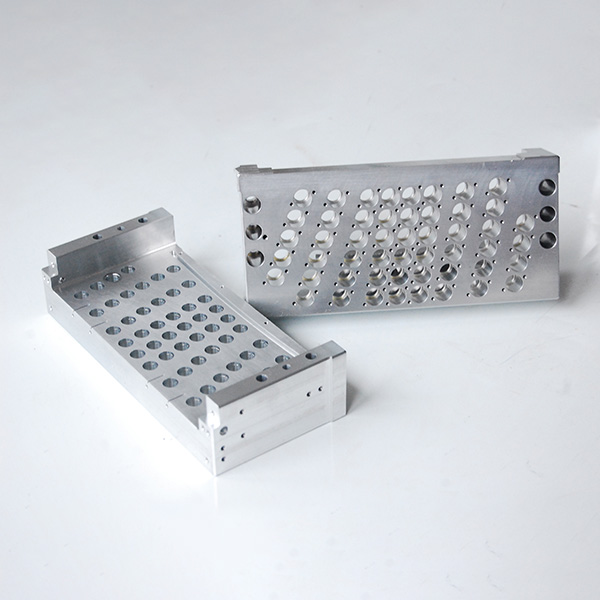
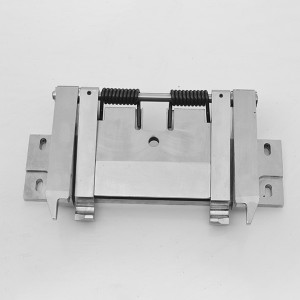
CNC drilling
parts
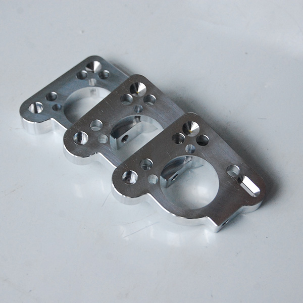
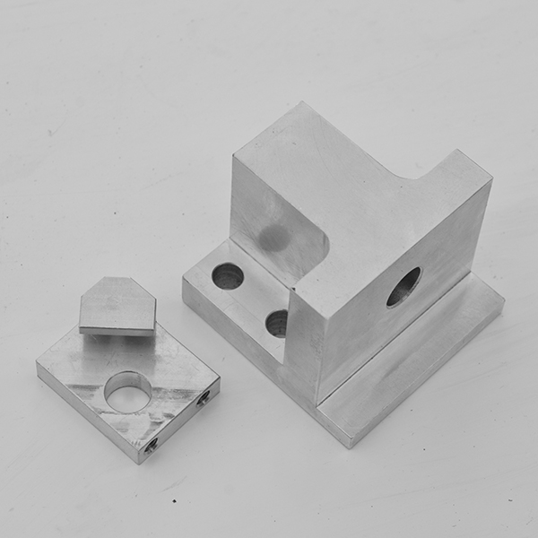
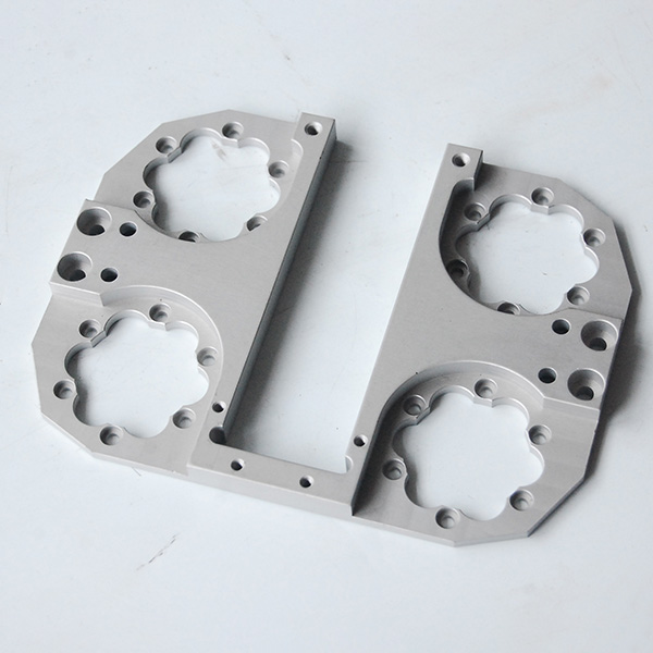
CNC machined
aluminum parts
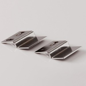
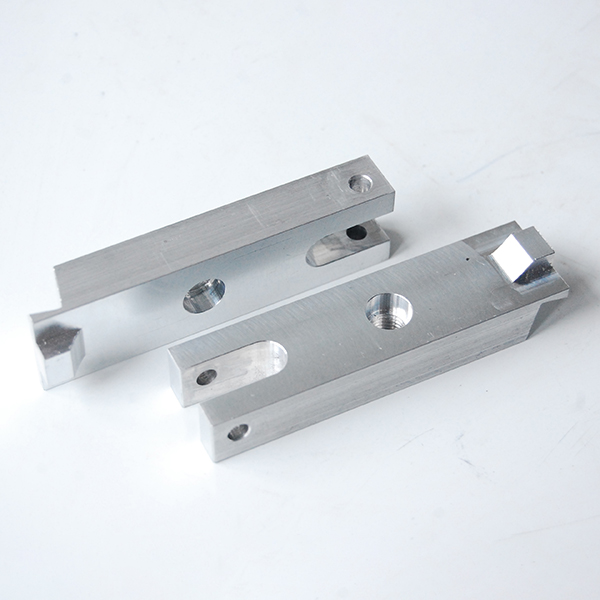
CNC machining
bended parts
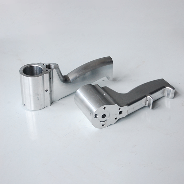
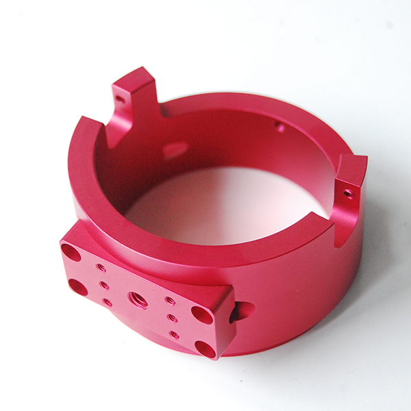
CNC machining parts
with anodizing
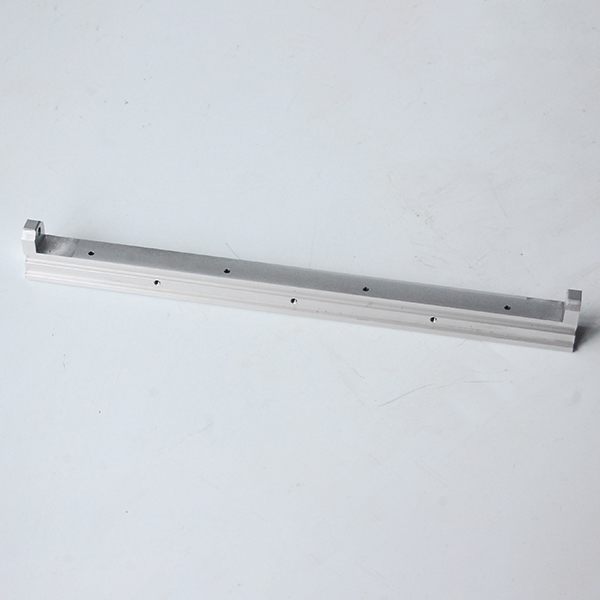
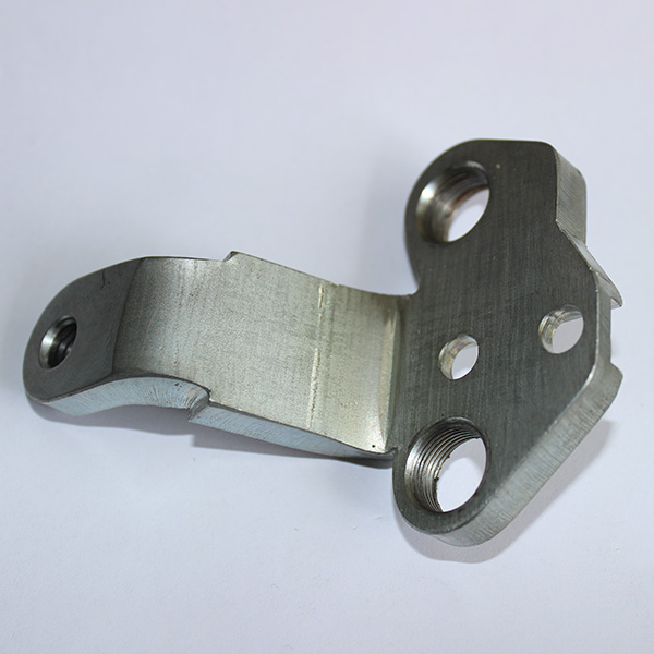
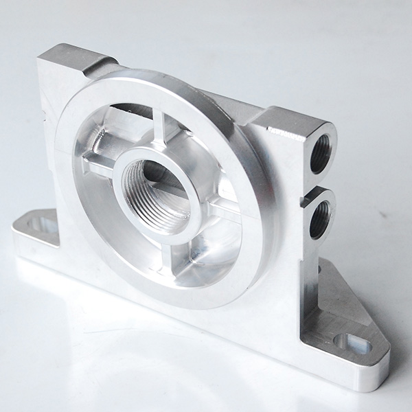
High precision
cnc parts
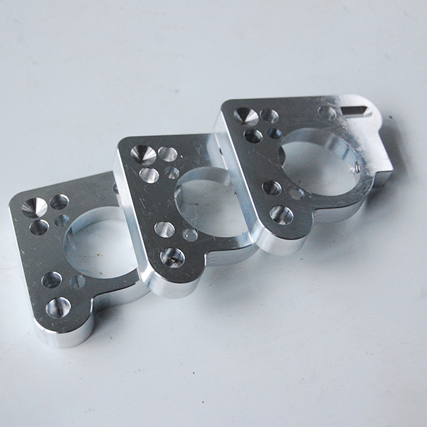
Precision aluminum casting
with machined and anodized
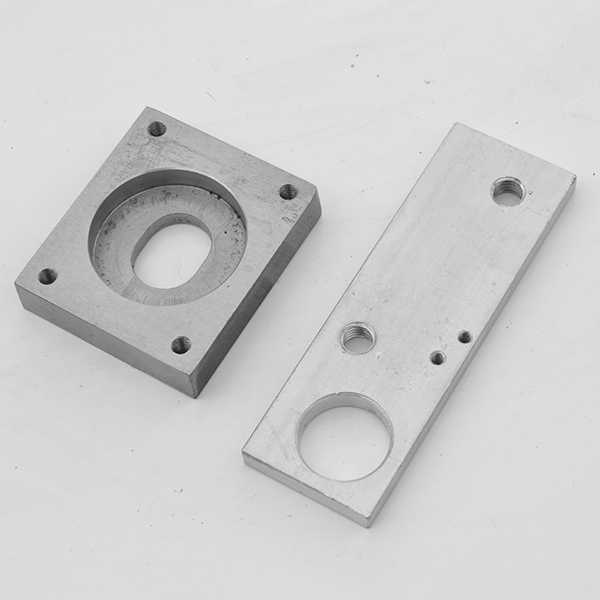
Precision cast aluminum
with machined
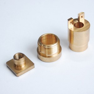
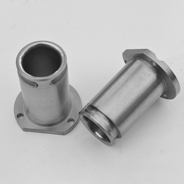
Steel cnc
machining parts